Stepper Motor
Written by Grace Lo, Rachel Yan, & Henry Sigel
Inspired by the quick vertical motion of a 3D printer build plate, a Stepper Motor with Integrated T8 Lead Screw is used to control the mechanical design of the flux chamber by opening and closing the chamber. It can be purchased as a spare part for Prusa 3D printers, although similar models can be found from 3rd party 3D printer parts vendors or Amazon. It uses Adafruit's TMC2209 Stepper Motor Driver Breakout Board to control the direction, step, and current flow. The current flow is used for the motor's holding torque and without it, the motor's position can shift. But since it is attached to a threaded metal rod with a self-locking nut, the change is negligible. Therefore, when the motor is not in use, the current flow is disabled to reduce power consumption and prevent the motor from overheating.
Pin Connections

Pin connections from the motor driver → Pico are as follows:
- VDD → 3V3(OUT) (pin 36)
- GND → GND
- DIR → GPIO 16 (pin 21)
- STEP → GPIO 17 (pin 22)
- EN → GPIO 18 (pin 24)
And on the terminal block:
- ⊕ → motor input voltage (12V)
- ⊖ → GND
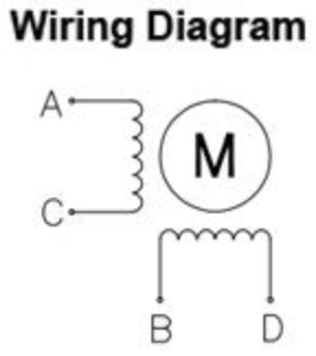
- For 1A/B and 2A/B, check the motor's datasheet for the 2 pairs of leads by inductor and their corresponding wire color. In this case, A & C are paired together and B & D.
Code
All code is in the CornellFluxChamber Github repository. The code for running the stepper motor is incorporated into flux_chamber.c.
Includes
The first lines of code in the C source file include header files. Don't forget to link these in the CMakeLists.txt file!
The following files are required to enable the GPIO pins for the motor driver.
#include <stdio.h>
#include "pico/stdlib.h"
Initializations
The C source file initializes the GPIO's as outputs. In addition, it immediately disables the motor using the enable pin to cut the current.
gpio_init(18);              // enable pin
gpio_set_dir(18, GPIO_OUT);
gpio_init(17);              // step pin
gpio_set_dir(17, GPIO_OUT);
gpio_init(16);              // direction pin
gpio_set_dir(16, GPIO_OUT);
gpio_put(18, 1);            // disable motor when not in use
Running the Motor
The motor code is wrapped in a move_motor function that takes in arguments for the direction and number of steps the motor should take, on the order of thousands. For demonstration purposes, the motor is run for the defined number of steps. However, it can be changed to run until a sensor sends a signal for it to stop (this configuration is used in the final flux chamber design). The function first enables current to the motor and defines the direction (0 for clockwise/up, 1 for counterclockwise/down). Then, the STEP pin is toggled for the amount of steps defined, which visibly is the length of time for the motor movement. Note that the for-loop keeps toggling the STEP pin because the stepper motor is triggered by rising edges, so one toggle means one step. The sleep_us(300) delay between toggles ensures the motor driver has sufficient response time for each step, which in this case is a stable frequency of 3333 Hz. This sleep time is subject to change depending on the motor model! For our current motor, the frequency can reach as high as 10 kHz, but it presents greater vibrations deemed unstable for our system. In comparison, the standard NEMA 17 stepper motor can only reach a frequency of 1 kHz.
// Function to move motor - 0 is cw up, 1 is ccw down
void move_motor(int direction, int steps) {
    gpio_put(18, 0);            // enable motor
    gpio_put(16, direction);
    for (int i = 0; i < steps; i++) {
        gpio_put(17, true);
        sleep_us(300);
        gpio_put(17, false);
        sleep_us(300);
    }
    gpio_put(18, 1);            // disable motor
}