Electronics Parts List
Note: Prices are prorated.
| Item | Part Number | Quantity | Price ($) | Notes |
|---|---|---|---|---|
| Raspberry Pi Pico (with Pre-Soldered Headers) | 1 | 5.00 | ||
| Figaro Methane Sensor | NGM2611-E13 | 1 | 28.00 | |
| Sensirion CO₂ Sensor | SCD30 | 1 | 33.24 | |
| MicroSD Card Breakout Board | 1 | 7.50 | ||
| MicroSD Card | 1 | 6.19 | ||
| Adafruit Stepper Motor Driver Breakout Board | TMC2209 | 1 | 8.95 | |
| NEMA 17 Stepper Motor with Integrated 300mm T8 Lead Screw (includes motor nut) |
1 | 26.99 | Adjust total length (motor body + lead screw) accordingly for a taller/shorter chamber; this one is ~31 cm. The motor body's top face should still follow these dimensions (for compatibility with limit switch PCB): 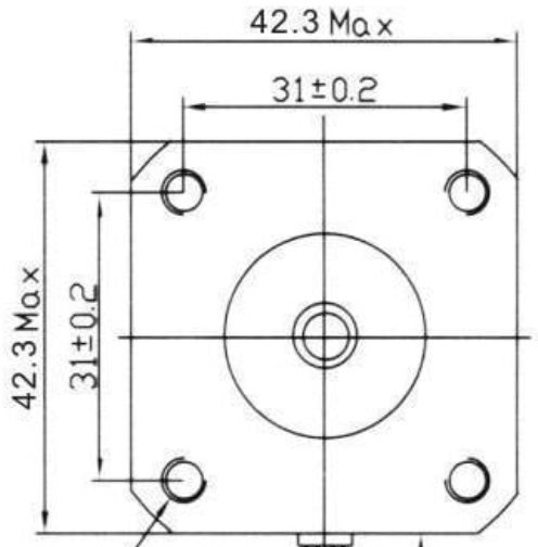 |
|
| Limit Switch | SS-5GL-3D | 1 | 1.77 | |
| Float Switch | PLS-031B-3PAI | 1 | 3.60 | |
| PCB (Main & Limit Switch) | 1 | 1.20 | The design files can be found in the CornellFluxChamber Github repository. The PCBs can be ordered from JLCPCB by uploading the two .zip files and keeping the default settings. |
|
| 2-Hole Screw Terminal 2.54mm Pitch | OSTVN02A150 | 3 | 2.61 | |
| Barrel Jack to Wire Leads Adapter | 1 | 2.00 | ||
| 1kΩ Resistor | 1 | 0.10 | ||
| NPN Transistor | 1 | 0.14 | ||
| 1x3 Male Header Pin | 1 | 0.10 | ||
| Female Socket Pin Headers: | ||||
| 1x5 | 1 | 0.10 | ||
| 1x7 | 1 | 0.10 | ||
| 1x8 | 1 | 0.10 | ||
| 1x10 | 1 | 0.10 | ||
| 1x20 | 2 | 0.20 | ||
| Total | 127.99 |
Tools:
- Soldering Iron
- Wire Stripper
- Diagonal Cutter
- Raspberry Pi Debug Probe (optional)
Electronics Instructions
The electronic system uses header pins to create a modular design, where components can be easily replaced in case of failure.
Solder.
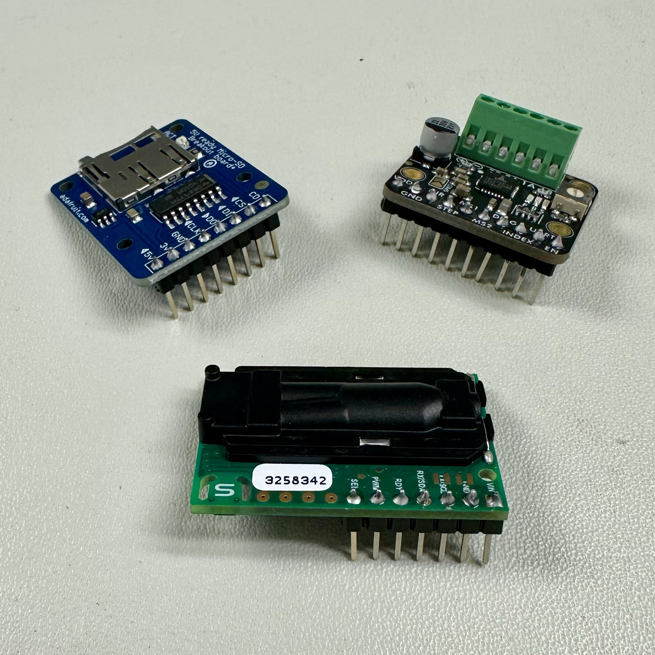
Male header pins (included in package) for the breakout boards (CO₂ sensor, microSD card breakout board, motor driver).
Header pins and other parts (screw terminals, 1kΩ resistor, NPN transistor, limit switch) for the PCBs.
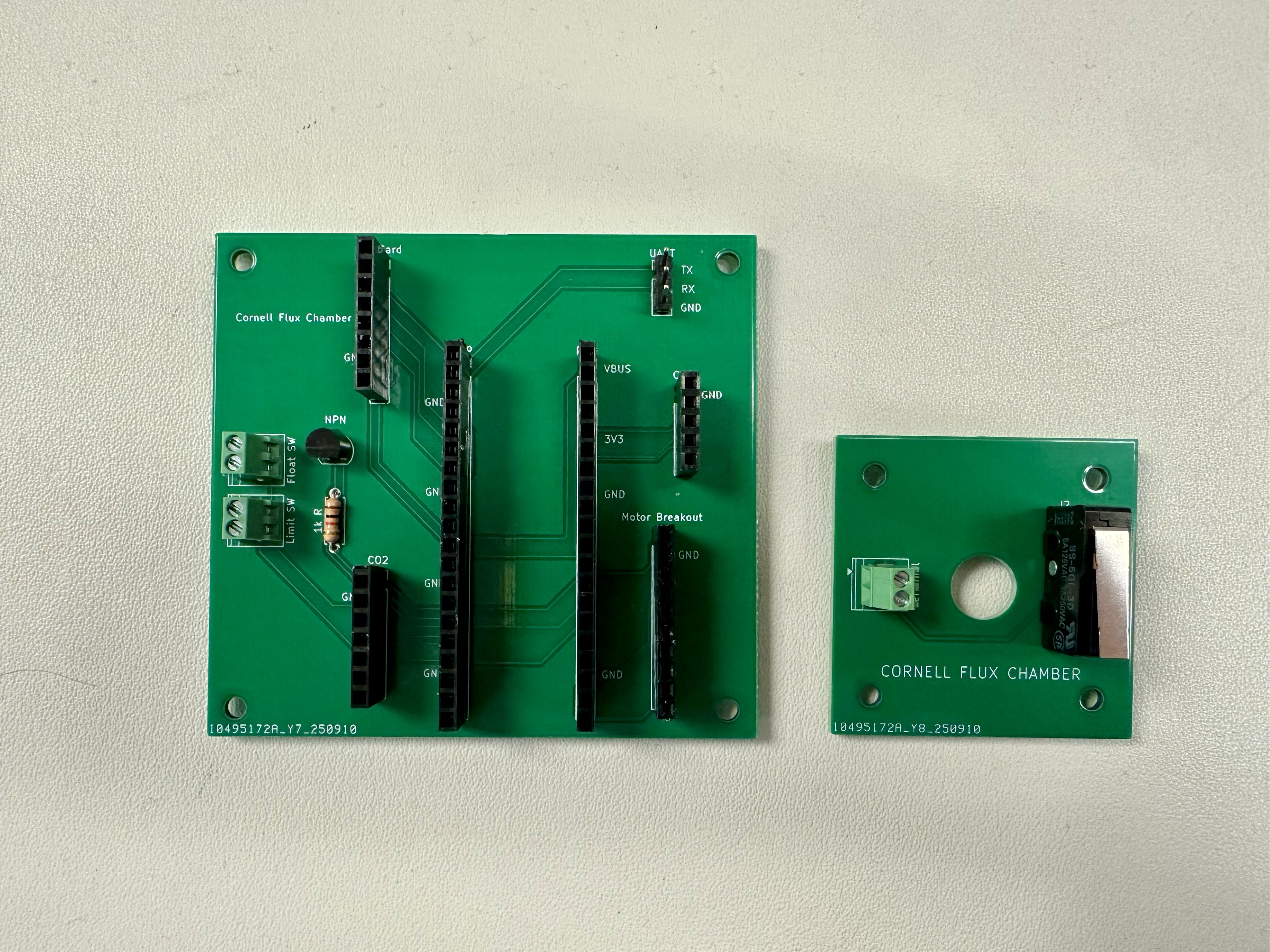
Use diagonal cutters to trim the ends of the limit switch and screw terminals to be relatively flush with the PCB (in particular, the limit switch PCB should lay flat on the motor - see step 6 of Chamber Instructions).
Cut excess motor cable (leave ~3-in) and strip the motor cable to access the 4 wires. For longevity, it is suggested to solder each of the multi-threaded wires.
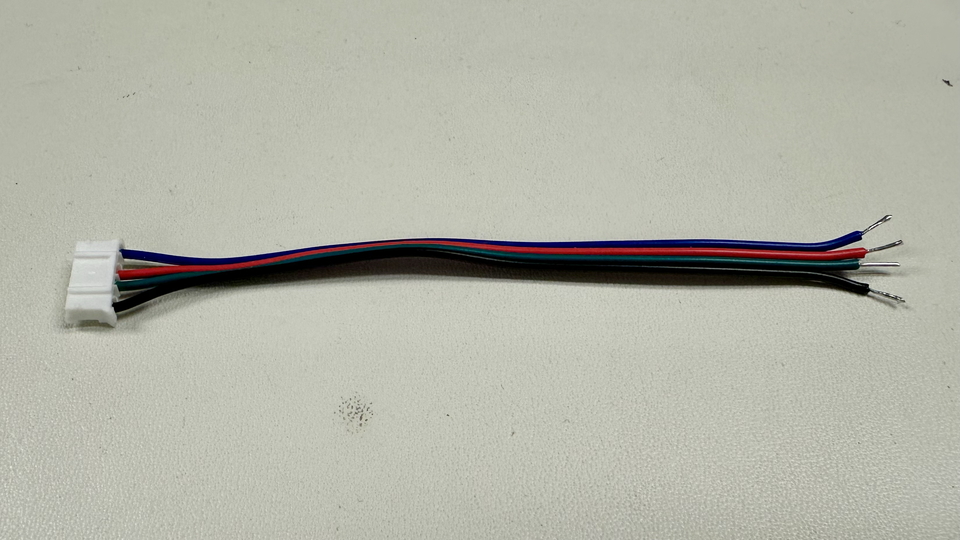
Screw the motor cable and the barrel jack to wire leads adapter to the screw terminal of the motor driver.
- The motor cable wires just need to remain aligned - starting from input 1B, we chose to order blue-red-green-black, although the reverse would work as well.
- For the wire leads, black/white corresponds to ground/⊖ and red corresponds to power/⊕.
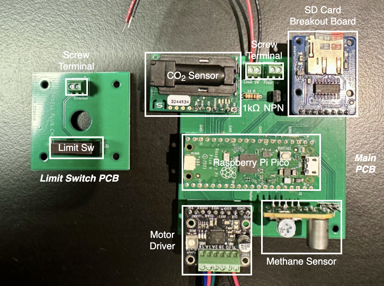
Plug in sensors according to the picture.
The screw terminal wires should be left out to connect later in the assembly process.
There are also detailed wiring diagrams in the Electrical design section of the main webpage.
Flash the code onto the Raspberry Pi Pico (see next section).
Flashing the Raspberry Pi Pico
The code must be flashed/loaded onto the Pico every time there is an update.
On your laptop's command-line interface (Terminal for macOS/Linux or PowerShell for Windows):
- Navigate to the folder you want to store the code using
cd [your_path] - Then clone the CornellFluxChamber Github repository using
git clone https://github.com/CornellFluxChamber/ChamberCode.git
- Navigate to the folder you want to store the code using
Download Visual Studio Code if you don't have it already and install the Raspberry Pi Pico and Serial Monitor extensions.


Click the Pico extension on the left sidebar and "Import Project" by changing the location to the
ChamberCodeproject folder (eg.[your_path]/ChamberCode/CornellFluxChamber).Note: We cloned the whole
ChamberCoderepository, but we only want to open theCornellFluxChamberproject.The chamber code has a
CUSTOMIZABLE PARAMETERSsection to change:- Filename
- Date/time
- Total sampling time per cycle
- Sampling interval between each measurement
- Total chamber flush time per cycle
- Debug boolean
For more information, see the Flux Chamber page.
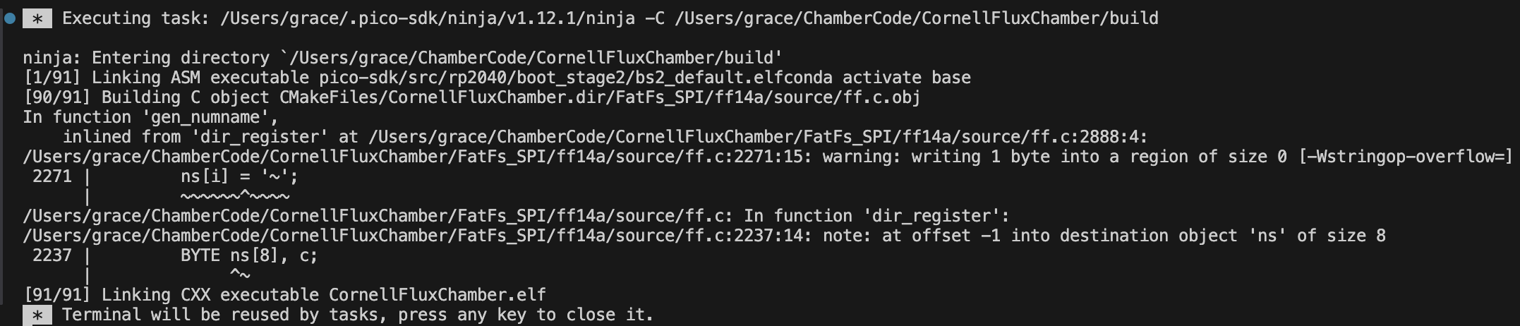
A new window will open with a list of the contents on the left. Click "Compile" at the bottom of the screen to build the project.
Note: There are 2 known warnings when compiling the code, but it does not affect the functionality of the system.
Hold down the Bootsel button on the Pico and plug the USB cable into your laptop to enter BOOTSEL mode. Then click the "Run" icon at the bottom of the screen to flash the Pico.
There are 2 ways to verify correct setup:
- Let the system run for 1 minute, then power it off and read the SD card contents.
- There is a serial monitor displaying real-time information about the running system for use during initial setup.
- Connect the Raspberry Pi Debug Probe via:
- PCB TX → debug probe RX (yellow)
- PCB RX → debug probe TX (orange)
- PCB GND → debug probe GND (black)
- USB → laptop
- Then go to the
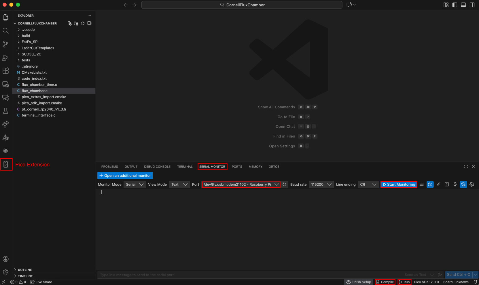
flux_chamber.cfile, find theCUSTOMIZABLE PARAMETERSsection, and changedebug_mode = true. - "Compile" the changes.
- Go to the "Serial Monitor" tab and set the port to the one ending in "Raspberry Pi." Then "Start Monitoring."
- "Run" it on the Pico.
- Connect the Raspberry Pi Debug Probe via:
Chamber Parts List
Note: Prices are prorated.
| Item | Part Number | Quantity | Price ($) | Notes |
|---|---|---|---|---|
| 1/8" Thick x 12" x 12" Acrylic | 2 | 10.00 | ||
| 1/2-in x 10-ft PVC Pipe 1/2-in x 2-ft PVC Pipe |
1 3 |
14.20 | 16-ft total cut into 12 x 1-ft and 4 x 10-in pieces. | |
| 1/2-in PVC 3-Way Elbow | 4 | 6.80 | ||
| 1/2-in PVC 4-Way Elbow | 4 | 8.00 | ||
| 7/8-in Stainless Steel Loop Clamp | 12 | 8.99 | ||
| 10-in Diameter PVC Flexible Duct | 14-in | 2.27 | Cut 14-in section & seal the top/bottom wire opening with caulk. | |
| Silicone Caulk | 1 | 8.88 | ||
| Pool Noodle | 2 | 2.00 | Cut 8 x 10.5-in pieces. | |
| Small Binder Clip | 4 | 0.40 | ||
| Nuts and Bolts: | ||||
| M3 × 0.5-mm x 6-mm Machine Screw | 92005A116 | 4 | 0.18 | |
| M3 × 0.5-mm x 10-mm Machine Screw | 92005A120 | 8 | 0.35 | |
| M3 × 0.5-mm x 40-mm Machine Screw | 92005A135 | 4 | 0.45 | Length of screw should match length of motor body (ie. 40-mm screw for a 39.5-mm body). |
| M3 × 0.5-mm Hex Nut | 90591A121 | 4 | 0.08 | |
| M3 Washer | 91166A210 | 8 | 0.18 | |
| #8-32 x 5/8-in Machine Screw | 90272A196 | 8 | 0.37 | Screw size is flexible as long as the screw fits a 6.5-mm hole. |
| #8-32 Hex Nut | 90480A009 | 8 | 0.16 | Nut size to fit chosen screw. |
| 1-in x 3-in Velcro | 1 | 0.29 | ||
| Waterproof Tarp | 1 | 0.70 | Cut 22-in x 22-in square. | |
| Electrical Tape | 1 | 2.98 | ||
| USB to 2.1mm DC Booster Cable - 12V Output | 1 | 6.50 | ||
| Portable Charger (not included in total price) | 1 | ~20.00 | ||
| Total | 73.78 |
Tools:
- Caulk Gun
- #2 Phillips Head Screwdriver
- Flathead Screwdriver (2.5-mm)
Chamber Instructions
Laser cut the acrylic top and support with templates provided in the CornellFluxChamber Github repository.
- If you do not have access to a laser cutter, drill holes for the acrylic top and replace the acrylic support with flexible lighting panel, which is easier to cut with heavy duty scissors/craft knife.
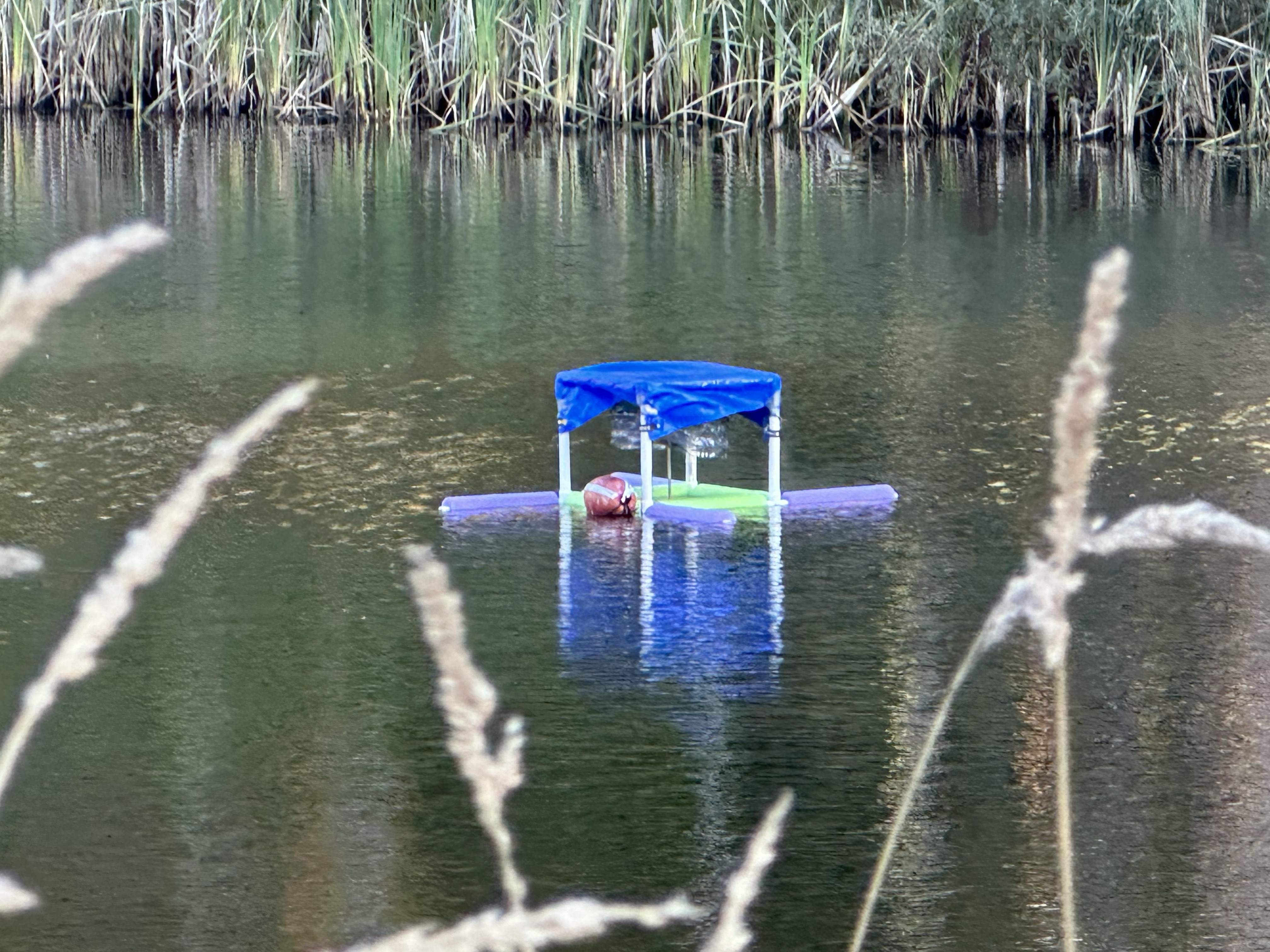
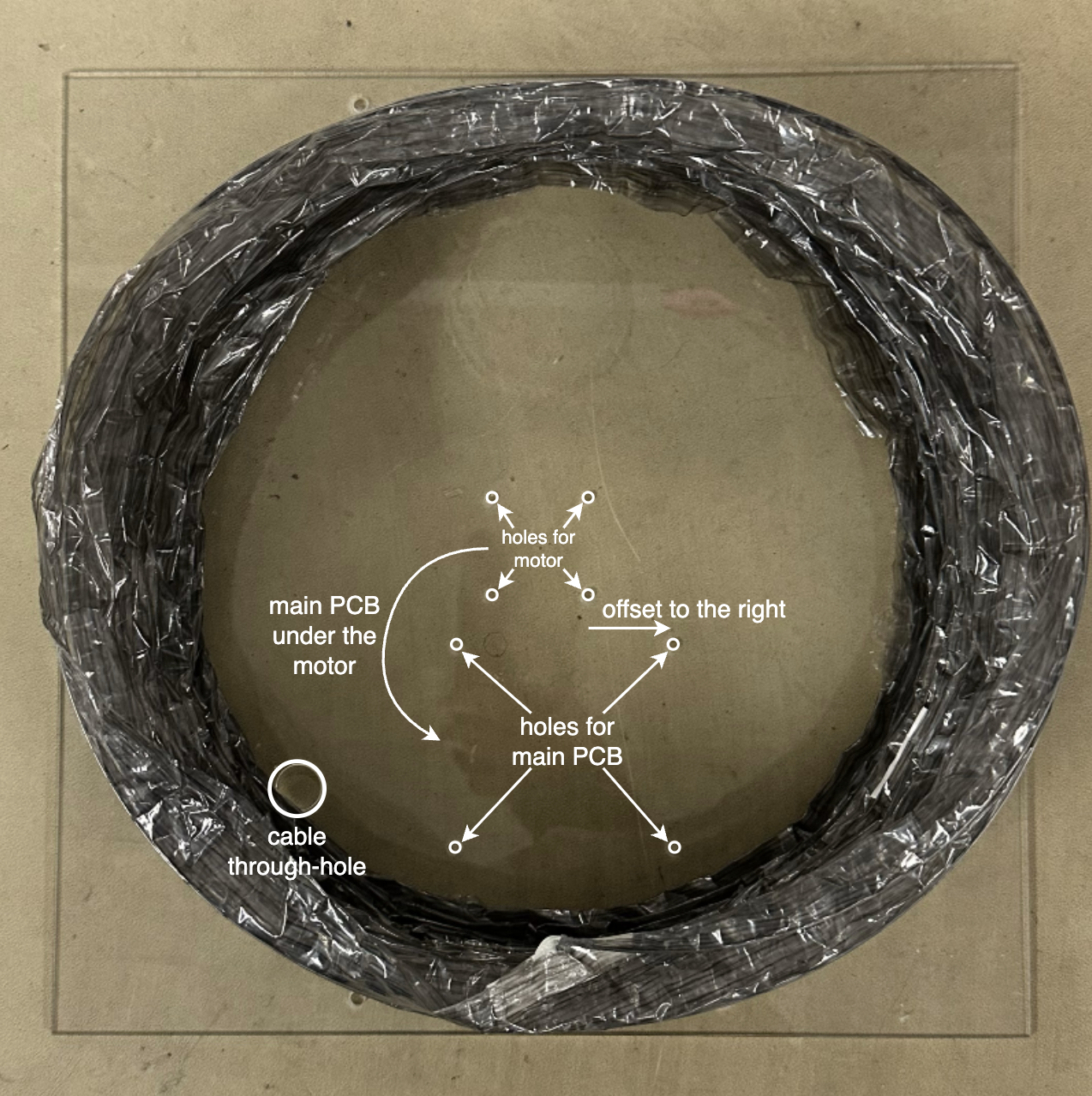
Orient the acrylic top according to the photo and caulk the duct, ensuring no air gaps. Let it dry before proceeding.
- Don't make the same mistake I did, double check your orientation or else the PCBs will not fit properly!
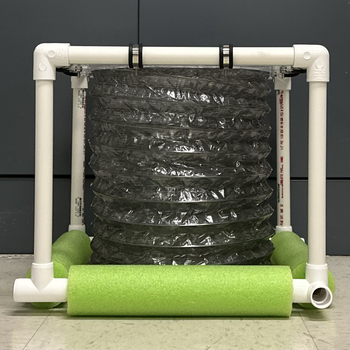
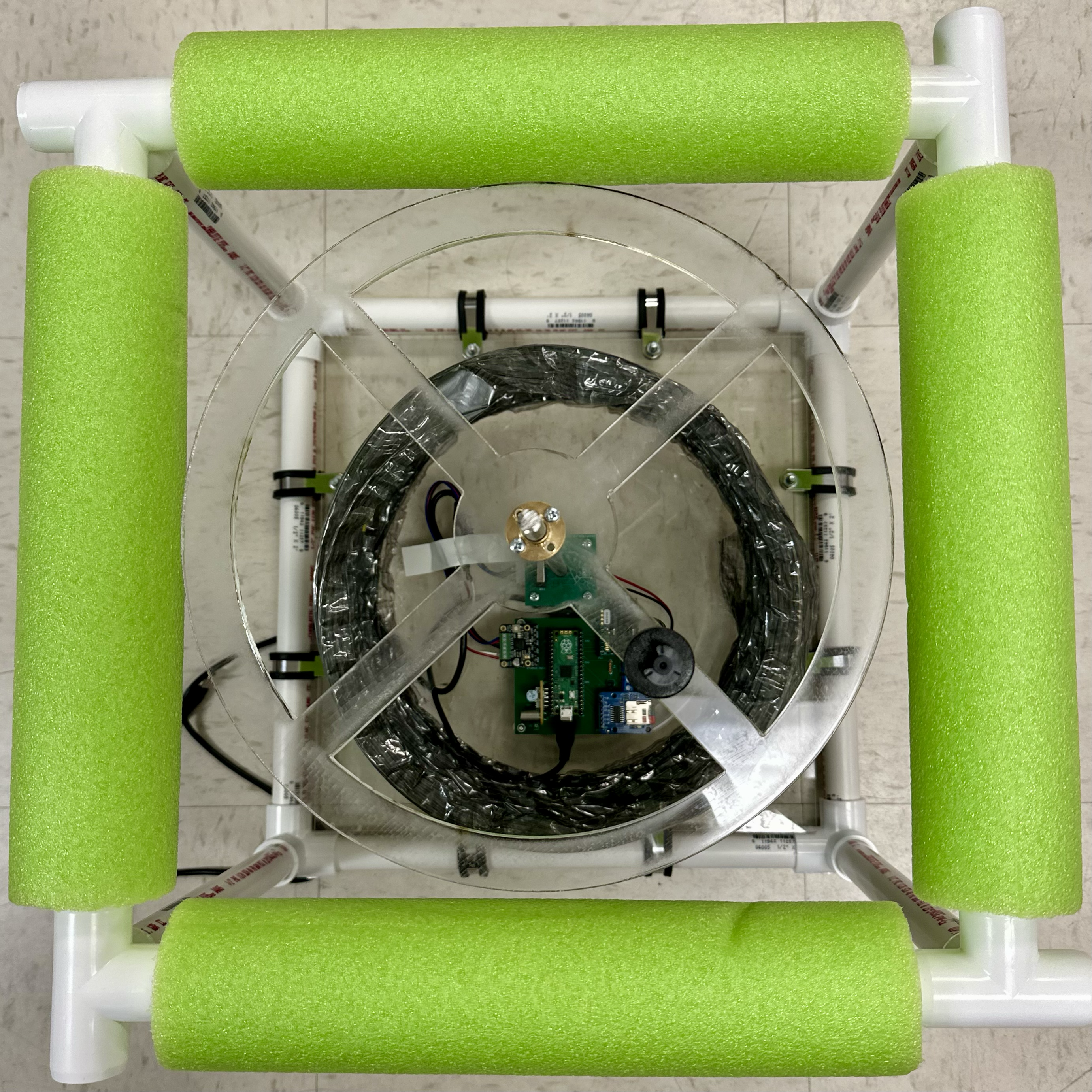
Build the structure.
- Thread pool noodles through 4 1-ft pipes for the base.
- Using the 10-in pipes as the sides, connect the pipes with 3-way elbows on the top and 4-way elbows on the bottom.
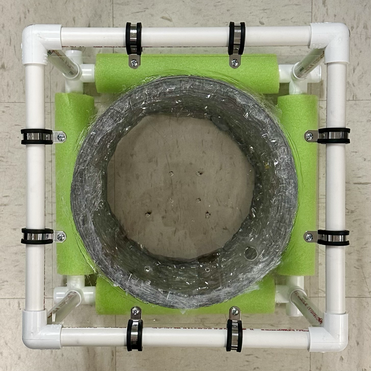
Secure the acrylic top to the structure using loop clamps and #8-32 nuts/screws.
- Tip: Squeeze the loop clamps to align its holes before threading the screw.
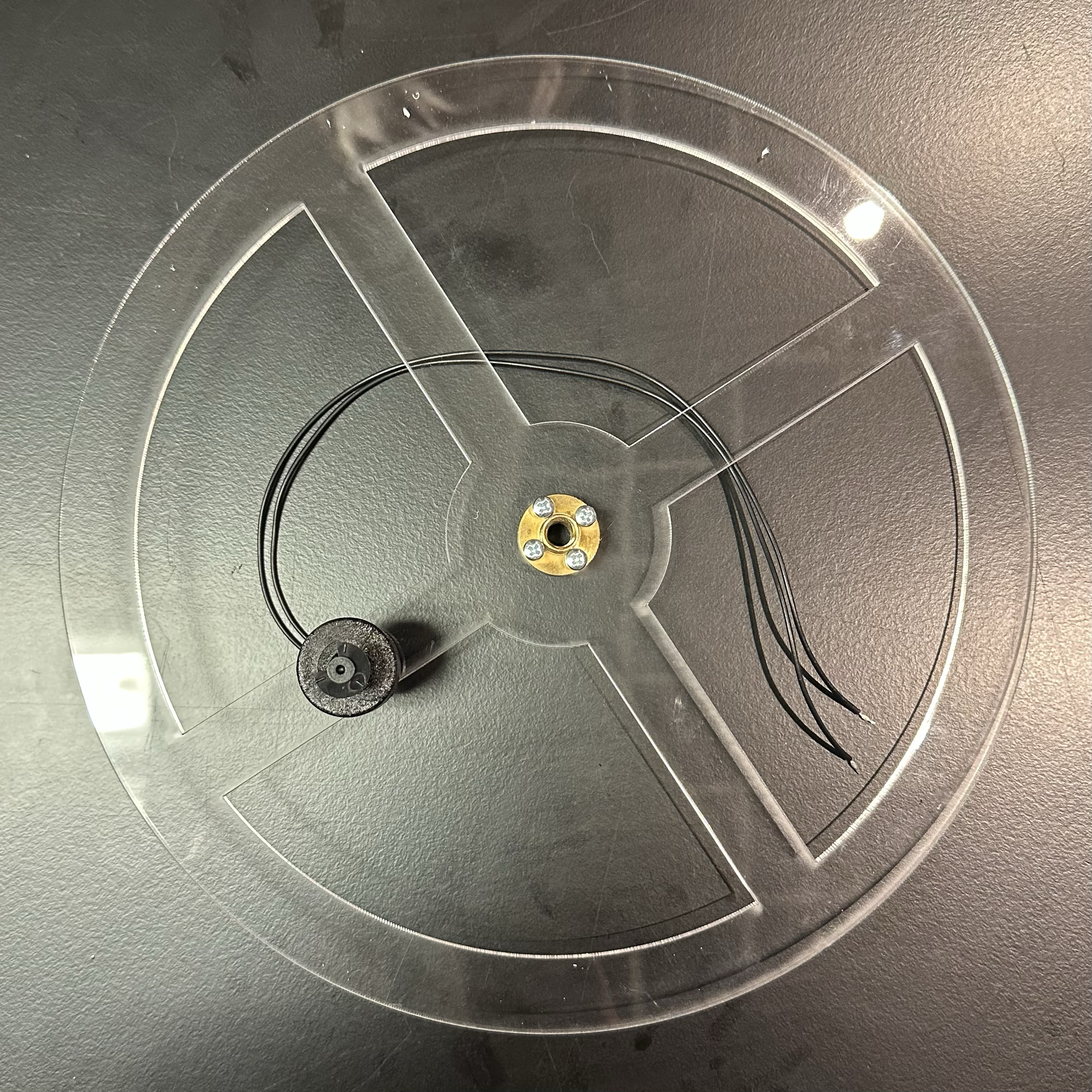
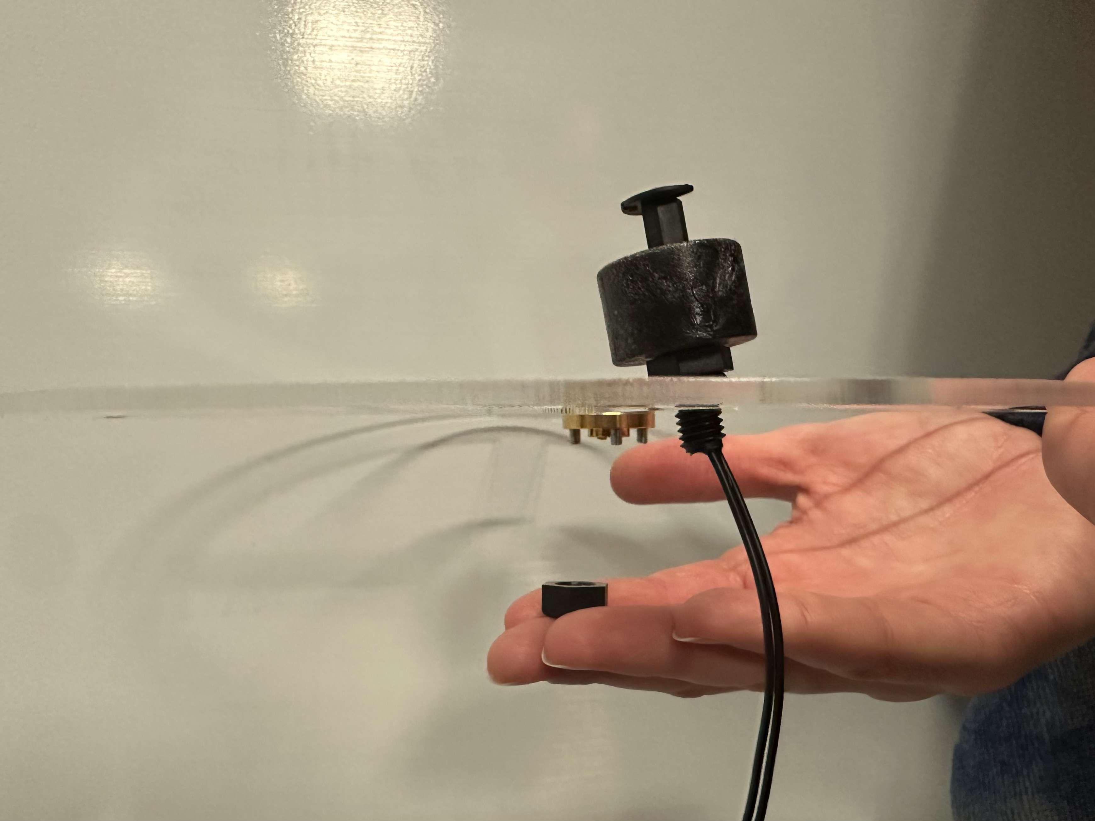
Attach the motor nut (included with the motor) and the float switch.
Thread the long end of the motor nut through the center of the acrylic support and attach it using 4 M3 x 10-mm screws.
Connect the float switch with the float facing up.
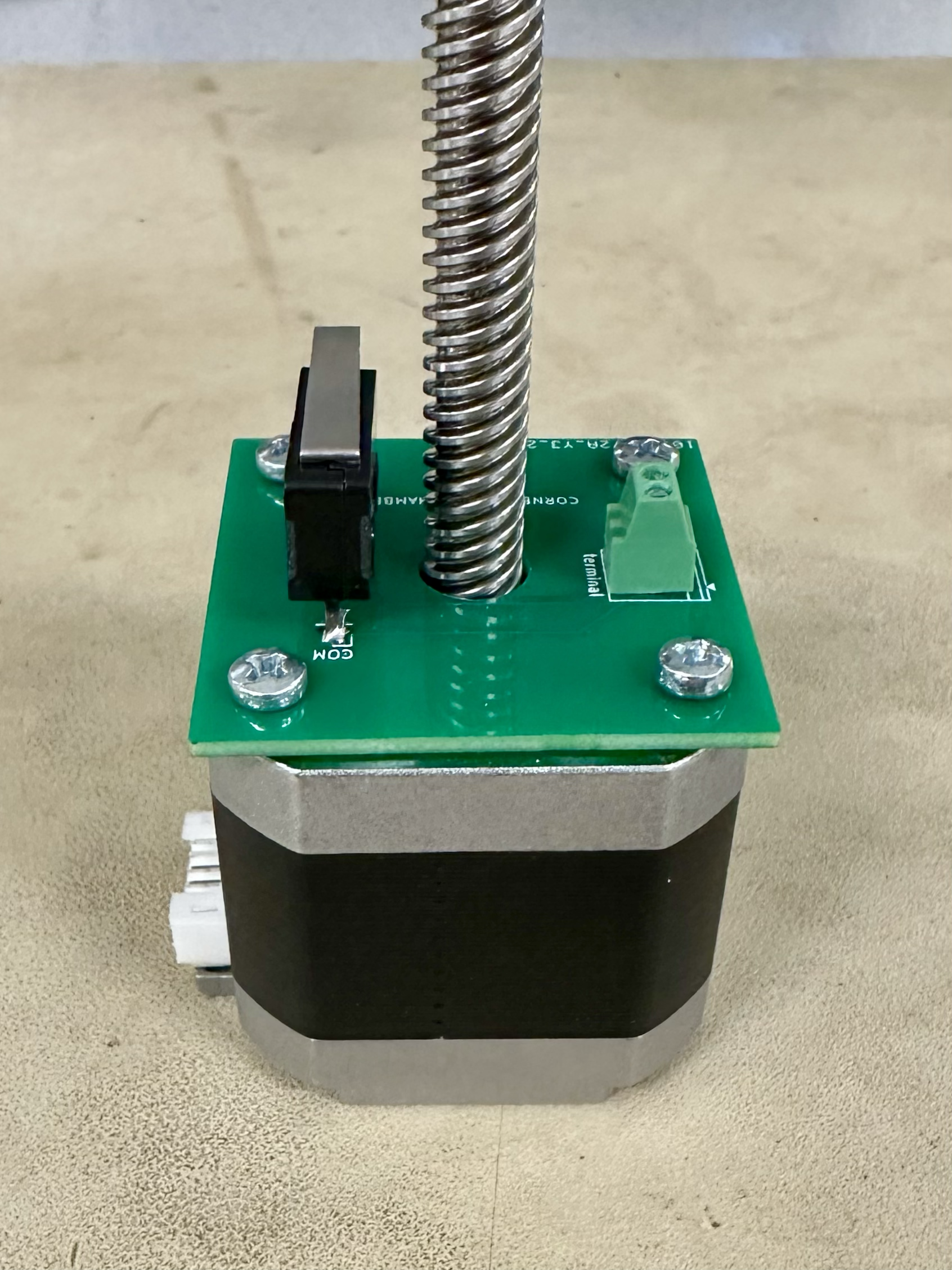
Mount the PCBs.
Remove the original screws in the motor and then screw the limit switch PCB to the underside of the motor using 4 M3 x 6-mm screws.
- Beware of tightening it too much as it could hinder motor movement.
- The limit switch and motor cable port should be on the same side.
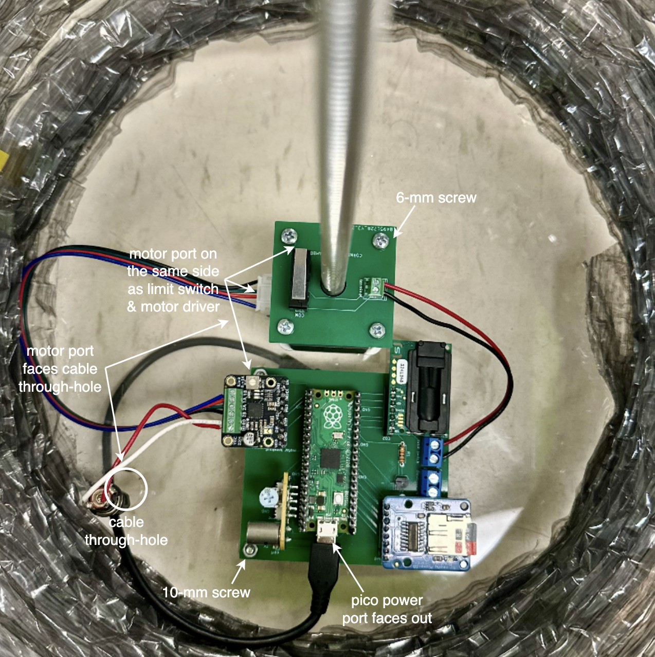
Mount the motor to the center of the acrylic top using 4 M3 x 40-mm screws, with washers on the acrylic side to distribute the forces.
- The motor should be oriented such that its cable port faces the cable through-hole of the acrylic.
Mount the main PCB to the acrylic top using 4 M3 x 10-mm screws. Again, the washers are placed on the acrylic side and nuts are secured on the PCB side.
- The PCB should be oriented such that the Raspberry Pi Pico power port faces outward and the motor driver is closer to the cable through-hole side of the acrylic.
Connect the limit switch wires between the PCBs, the 4-wire motor cable between the motor and the main PCB, and the wire lead adapter to the motor booster cable.
Pull the motor booster cable and Pico power cable through the cable through-hole toward the side of the acrylic, then caulk the hole to seal it shut.
Thread the acrylic support piece onto the motor rod, with the float of the float switch facing outward. Rotate the support piece until it is at the desired maximum height (when the canopy is fully open, the float switch should touch the surface of the water to indicate the end point).
- Now is the time to screw the float switch wires into the main PCB.
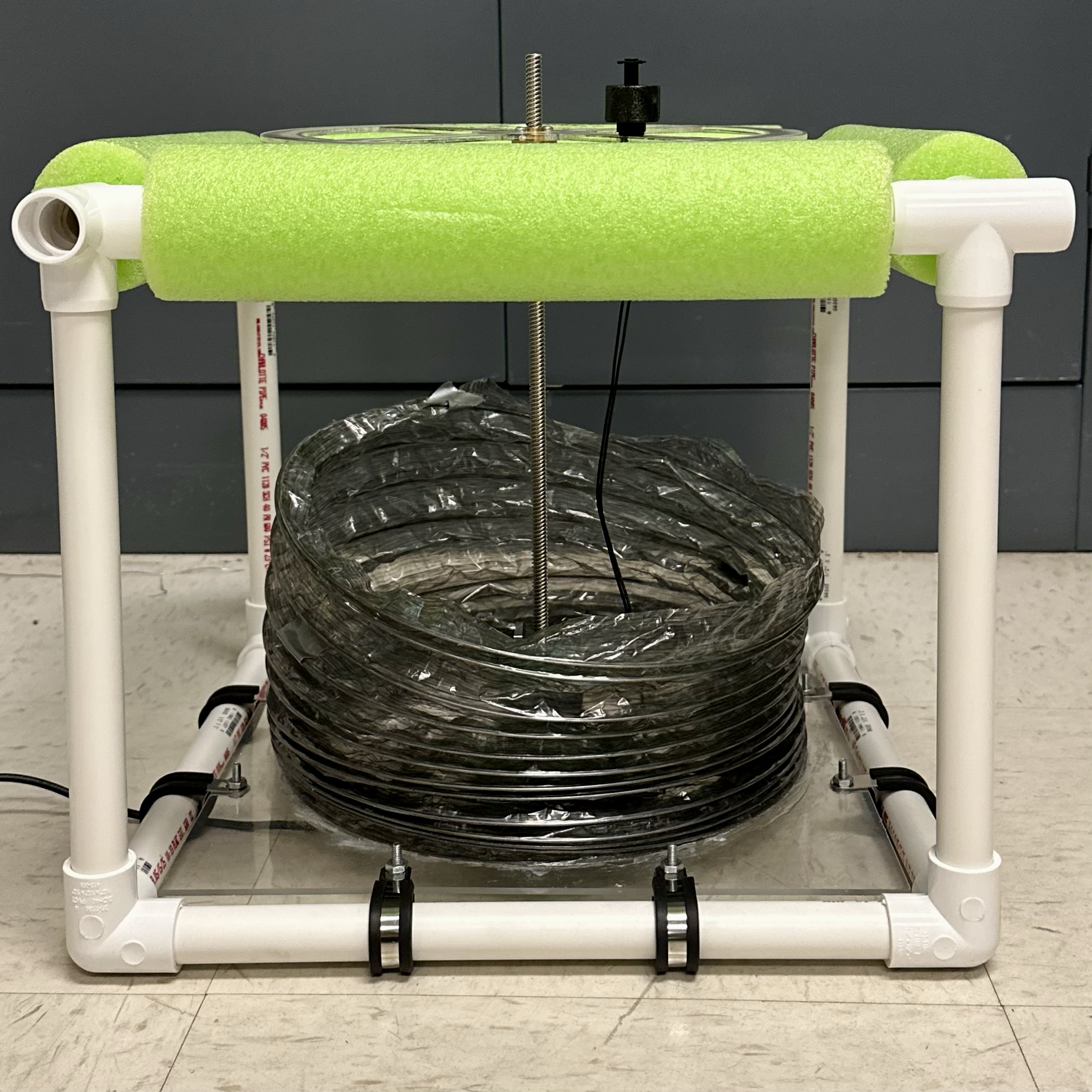
Fully extend the duct and use binder clips to secure it to the acrylic support.
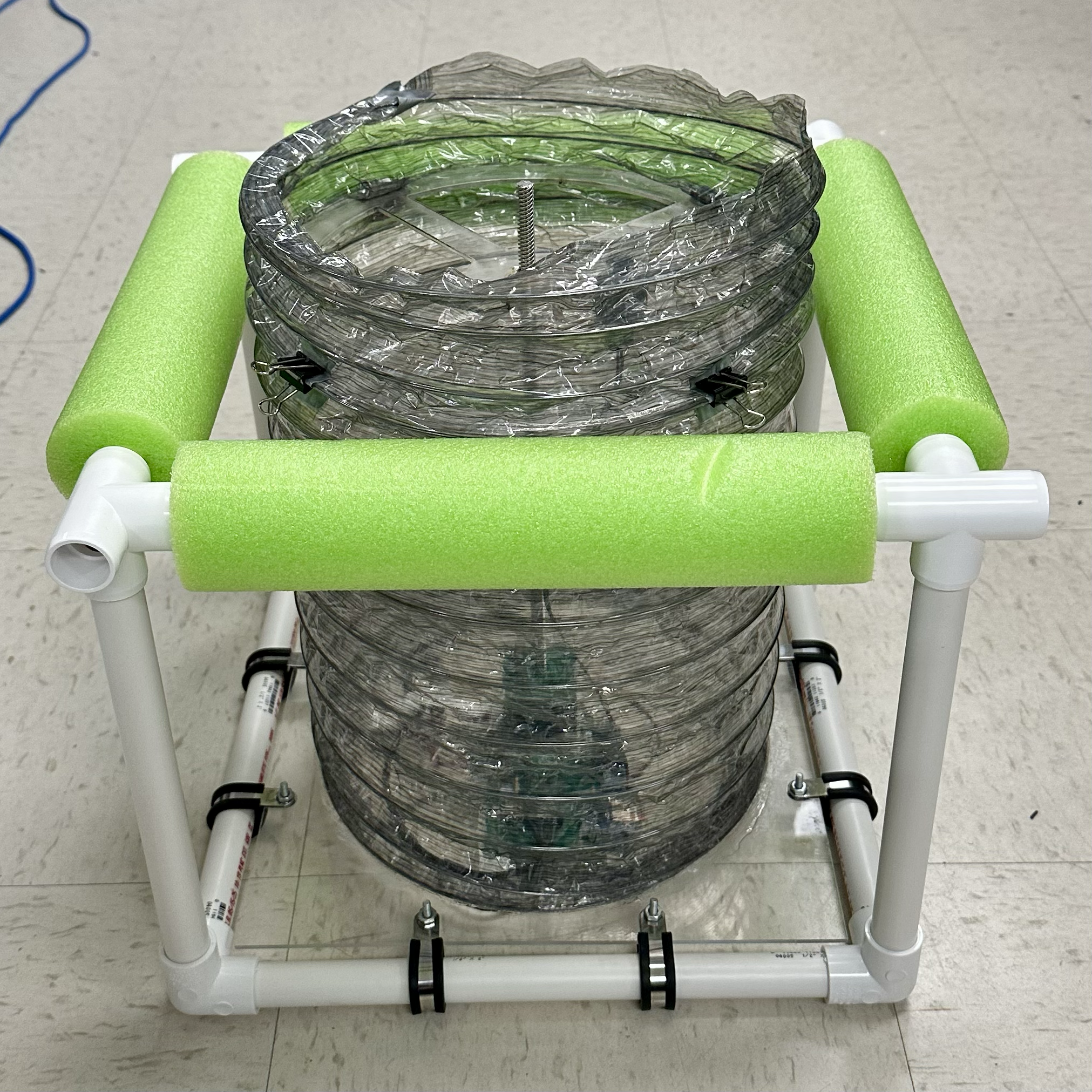
Finishing touches.
Flip the chamber over and place electrical tape over the exposed screws to electrically isolate them.
Secure the portable battery to the top of the structure using velcro on the battery and acrylic.
Place the tarp over the chamber such that rain water can fall off the edges, securing each corner to the structure using and duct tape.
For extra buoyancy, thread pool noodles on the last 4 1-ft pipes and connect these support legs to the 4-way elbows of the chamber structure.